
In today’s interconnected world, efficient data flow is crucial, and routing protocols act as guides for network traffic. The Border Gateway Protocol (BGP) stands out as a strong option, especially in virtualized setups where it enables flexible routing.
In this blog post, we explore Nutanix Flow Virtual Networking (FVN) and how it uses BGP routing. We’ll understand why businesses adopt this technology for smoother, scalable, and secure network communication in Nutanix FVN’s Virtual Private Cloud (VPC). Whether you’re an IT pro enhancing your network or a curious learner diving into routing, this look at BGP in Nutanix VPC explains its practical uses.
Understanding BGP Routing
In the intricate tapestry of networking protocols, the Border Gateway Protocol (BGP) stands as a beacon of intelligence and adaptability. Unlike interior routing protocols that focus on within-network communication, BGP operates at the edge of networks, facilitating inter-domain routing on a global scale. Its unique characteristics and mechanisms make it an invaluable tool for orchestrating the flow of data across diverse and complex network landscapes.
Key Characteristics of BGP
Path Vector Protocol: BGP operates as a path vector protocol, distinguishing itself from distance-vector and link-state protocols. Instead of focusing solely on the shortest path, BGP factors in multiple attributes, known as path vectors, when making routing decisions. This flexibility allows BGP to accommodate diverse metrics and policy considerations.
Policy-Based Routing: BGP’s ability to incorporate various attributes in its decision-making process makes it ideal for implementing policy-based routing. Network administrators can define specific policies to control traffic flow, taking factors like network performance, cost, and security into account.
Loop Prevention: BGP is equipped with robust mechanisms to prevent routing loops, a common challenge in complex networks. The use of path attributes and the Autonomous System (AS) concept ensures that routes are not inadvertently cycled, enhancing stability and reliability.
Autonomous Systems (AS): BGP introduces the concept of Autonomous Systems, which are individual networks or network domains that are managed independently. This hierarchical structure allows BGP to scale effectively while maintaining logical separation between different network entities.
BGP in the Modern Network Landscape
BGP’s significance extends beyond the confines of traditional networks. It plays a crucial role in connecting different organizations, service providers, and cloud environments. BGP is the backbone of the global Internet routing system, enabling communication between diverse networks across the world.
BGP Inside Flow Virtual Networking (FVN) VPCs
FVN leverages the strength of BGP to enable dynamic routing within the boundaries of a VPC. By integrating BGP routing mechanisms, Nutanix empowers organizations to optimize data flow, enhance network performance, and achieve seamless connectivity within their virtualized environments.
In the following sections, we will explore how BGP routing is integrated within the structure of Nutanix FVN VPCs. We will delve into the components, configuration steps, and real-world use cases that illustrate the transformative impact of BGP routing within the Nutanix ecosystem.
Key Components of BGP Routing in Flow Virtual Networking (FVN):
The architecture of BGP routing in FVN is underpinned by several key components, as illustrated in the following figure. These components work together to enable dynamic and optimized routing within VPCs.
Let’s delve into these foundational elements that define the BGP routing landscape within the Nutanix ecosystem:
1. BGP Gateway (GW): Control Plane Management
The BGP Gateway (GW) serves as a central control unit for BGP routing within FVN. It manages the exchange of routing information, facilitating effective communication between internal and external networks. In Nutanix FVN, this function is deployed in the form of a virtual machine (VM).
2. VPC Gateway and AHV Host: Data Plane Handling
The VPC Gateway is responsible for handling data plane operations, guiding the flow of network traffic between the VPC subnets and external networks.
In VPC external connectivity, Nutanix AHV hosts play a crucial role in data plane management, facilitating the seamless passage of data while maintaining virtualization boundaries.
3. Externally Routable Prefixes (ERP): Defining Routing Scope
Users define Externally Routable Prefixes (ERP) to specify which subnets participate in BGP routing. This allows for selective control over the routes that are advertised and propagated from within VPCs.
4. Integration with Nutanix Ecosystem: Prism Central (PC)
Prism Central (PC) serves as the management interface for configuring and overseeing BGP routing within Nutanix FVN. It offers a centralized platform for seamless integration and network management.
These essential components form the backbone of BGP routing within FVN, providing the bricks for dynamic and efficient routing operations. As we dig deeper, we’ll explore the practical aspects of configuring and utilizing these components to achieve optimal network performance and connectivity.
Use Cases for BGP Routing in Nutanix FVN VPC:
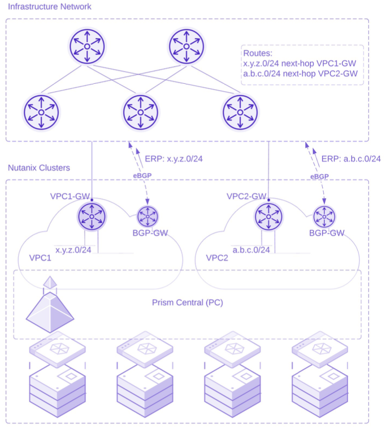
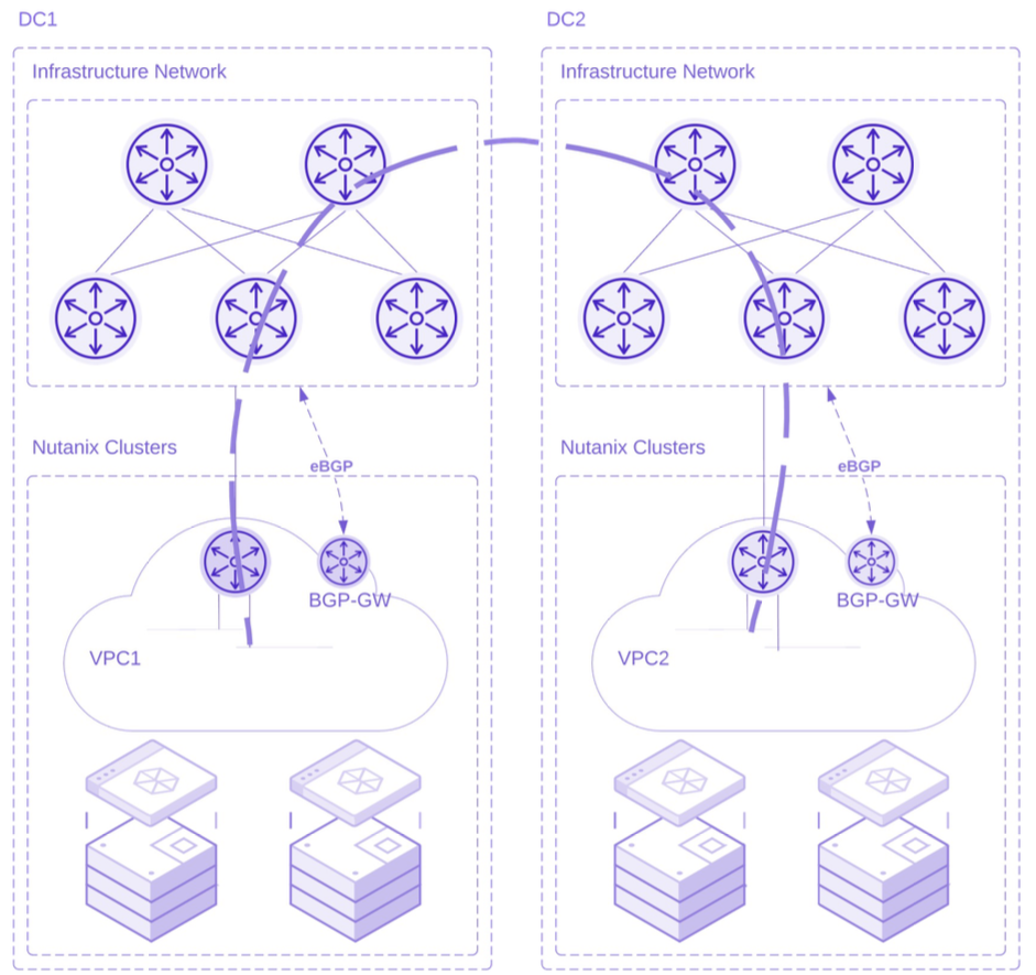
Multi-Site Network Optimization:
BGP routing within VPCs proves invaluable for organizations with a distributed presence across multiple sites. In this scenario, BGP acts as a unifying force, seamlessly connecting geographically dispersed VPCs. Administrators can leverage BGP to advertise routes between VPCs, enabling efficient communication and data exchange across different sites. This fosters a cohesive network environment, simplifying resource access, application deployment, and workload mobility. Whether managing regional branches or central data centers, BGP-powered multi-site connectivity in Nutanix FVN enhances operational agility and minimizes the network complexity, ultimately delivering a seamless user experience.
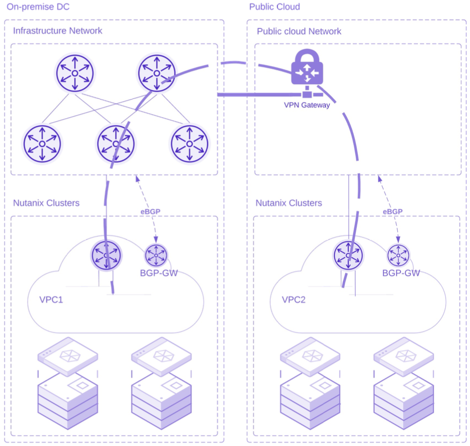
Hybrid Cloud Synergy:
The convergence of on-premises infrastructure and cloud resources defines the hybrid cloud landscape, and BGP routing in Nutanix FVN plays a pivotal role in achieving synergy between these domains. By employing BGP, organizations can establish dynamic connections between their Nutanix-powered VPCs and public cloud providers (Nutanix NC2 or native public cloud deployments). This interconnection empowers applications and workloads to seamlessly traverse between environments, facilitating workload migration, disaster recovery, and bursting to the cloud. BGP routing ensures that data flows optimally and securely, maintaining consistent performance and availability regardless of the underlying infrastructure. Nutanix FVN’s BGP capabilities prepare the path for a harmonious hybrid cloud strategy, enabling enterprises to exploit the potential of both on-premises and cloud resources.
Legacy Network Integration and Modernization:
BGP routing within Nutanix FVN VPCs serves as a bridge between legacy networks and modernized infrastructures. Many organizations operate within complex environments where legacy systems coexist with cutting-edge solutions. By implementing BGP, businesses can seamlessly integrate their existing network setups with Nutanix FVN, facilitating a gradual and strategic migration. BGP enables controlled route advertisement and exchange, allowing legacy and modern networks to communicate efficiently while preserving operational continuity. This integration streamlines the transformation journey, enabling organizations to modernize their network architecture at their own pace, without disrupting ongoing operations. The result is a harmonious coexistence of legacy and contemporary elements within a unified networking framework.
These diverse use cases underscore the versatility and transformative potential of BGP routing in FVN. Whether optimizing multi-site connectivity, orchestrating a hybrid cloud strategy, or facilitating legacy network integration, BGP empowers organizations to architect robust, agile, and seamlessly interconnected network environments.
BGP Gateway Deployment Options: Exploring VLAN-Based and Overlay Subnet Options
When it comes to deploying the BGP Gateway (BGP-GW) within Nutanix FVN, as covered in the Nutanix Bible, you’ll find two distinct options, each offering its unique approach to optimizing network communication. The foundation of both options centers around the concept of the Service VPC, which, for the sake of clarity, we’ll refer to as “blue-VPC” in the following figures.
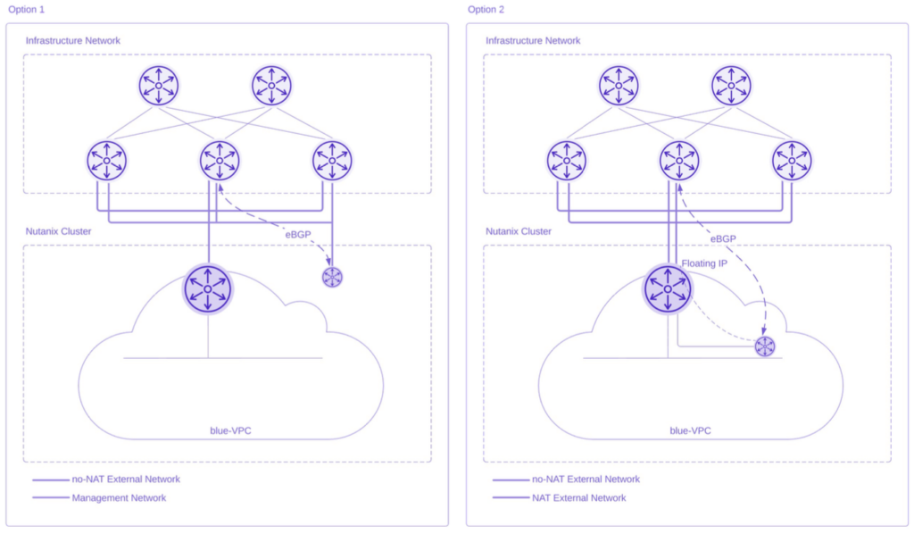
Option 1: VLAN-based BGP-GW deployment
In the first option, the deployment of the BGP-GW takes place within a VLAN, strategically positioned to ensure direct accessibility from the upstream router. This configuration offers a straightforward and efficient path for routing and communication. The BGP-GW acts as a dedicated BGP speaker serving a VPC (blue-VPC) and orchestrating the exchange of routing information with external networks.
Option 2: BGP-GW on overlay subnet and Floating IP
Alternatively, the second option involves deploying the BGP-GW within an overlay subnet, potentially located within the same Service VPC (blue-VPC). This deployment is orchestrated in a manner that makes the overlay subnet reachable through the application of a Floating IP.
The Floating IP plays a central role in facilitating access to overlay VMs from external networks. When there’s a requirement for an overlay VM to be reachable from the external network, the Floating IP concept comes into play. Users can designate a Floating IP that belongs to the NAT external network. This acts as a public IP, enabling external connectivity to the specific overlay VM.
Both options are strategically designed to enhance network efficiency and flexibility within the Nutanix FVN ecosystem. The decision between them hinges on factors such as network architecture, accessibility requirements, and optimization objectives. For optimal simplicity and streamlined management, our suggestion is to opt for the first option. This option not only ensures a more straightforward implementation but also offers notable advantages in terms of network architecture and deployment strategy.
By selecting the VLAN-based deployment of the BGP-GW, you’re opting for an approach that prioritizes simplicity and ease of management. This option eliminates the need to attach the VPC to the NAT external network, simplifying the overall network topology. The BGP-GW, serving as a dedicated BGP speaker within the Service VPC (blue-VPC), can be strategically positioned within a VLAN that is directly reachable from the upstream router.
The benefits of this approach extend beyond simplicity. Notably, it affords the flexibility to deploy the BGP-GW on a dedicated management cluster. In enterprise and large-scale deployments, the management cluster assumes the crucial role of hosting management workloads. By housing the BGP-GW within the management cluster, you enhance the separation of concerns and isolate critical networking functions, contributing to a well-organized and efficient infrastructure.
VPC BGP Deployment: A High-Level Overview
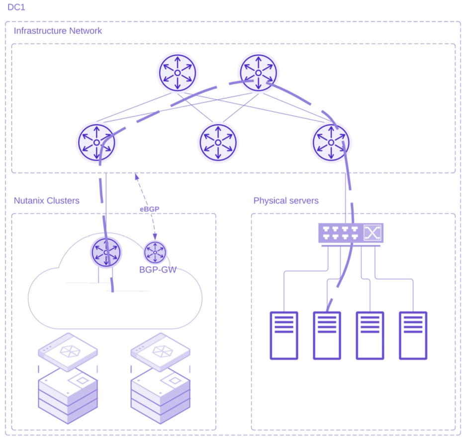
Before we embark on the step-by-step journey of configuring BGP routing within FVN, let’s first gain a high-level perspective of the target deployment. The visual representation below encapsulates the essence of our BGP routing configuration, showcasing the interplay between the infrastructure network and Nutanix clusters, while highlighting the pivotal elements and connections that constitute the dynamic routing environment.
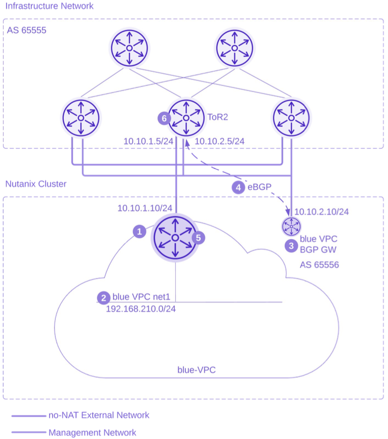
In this diagram, we observe the structured arrangement where the infrastructure network forms the upper stratum, and the Nutanix clusters reside below. A key focus of our configuration revolves around the VPC, which is attached to “ToR2,” an upstream router. ToR2 plays a dual role, with one interface connected to the no-NAT External Network and another to the Management Network. Our BGP Gateway (BGP-GW) is connected to the Management Network, serving as the VPC BGP speaker.
Within this orchestrated setup, we have the distinct goal of advertising the subnet 192.168.210.0/24 from the VPC, called “blue-VPC”. As we navigate through the subsequent steps, this high-level overview will serve as our guiding map, grounding us in the placement and connections that underpin our BGP routing configuration within Nutanix FVN.
BGP Deployment Inside VPC: Step-by-Step
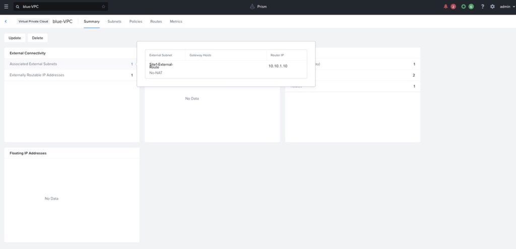
Creating a dynamic BGP routing environment within FVN begins with the creation of a dedicated VPC, named “blue-VPC” (marked as number 1 in the preceding figure). To enable communication with external networks, an external subnet of type No-NAT is attached to the VPC. During this phase, you should define the ERPs that are destined for advertisement. For instance, we choose to advertise the ERP 192.168.210.0/24.
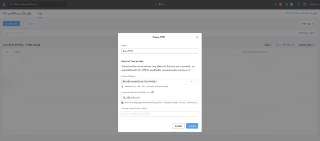
As the VPC is created, it is assigned an IP address from the external subnet’s address range, in our example the Router IP address of the blue-VPC is 10.10.1.10/24.
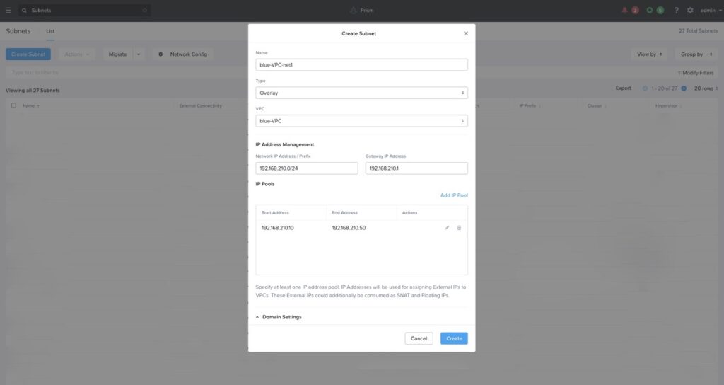
Once the VPC is created, the next step involves creating a subnet known as “blue-VPC-net1” (number 2 in fig. 6) that resides within the “blue-VPC.” This subnet, allocated the IP address 192.168.210.0/24, is the routable VPC subnet.
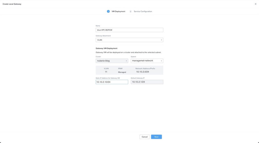
The BGP-GW is the central part of the Nutanix FVN dynamic routing function. The BGP-GW acts as the orchestrator of routing information used for communication between the VPC and external networks. Users are presented with the option of attaching the BGP-GW either to a VLAN or a VPC subnet accessible behind a Floating IP. For instance, in the context of enterprise or large-scale deployments, adhering to Nutanix Validated Design (NVD) recommendations, the BGP-GW may be placed within the management cluster. Here, it is attached to the Management Network (10.10.2.0/24), a VLAN within the Nutanix cluster signed to accommodate management workloads. In this example we allocate the IP address 10.10.2.10/24 to the BGP-GW (number 3 in fig. 6).
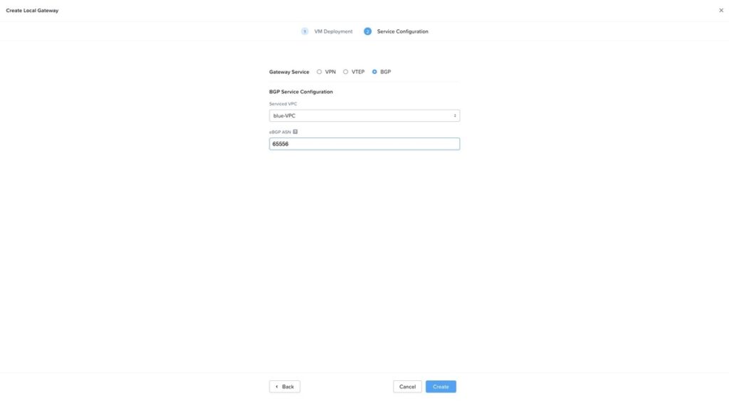
Once the IP address of the BGP-GW is selected, we associate it to the blue-VPC VPC and assign the AS number to it. In this example, we specify the AS number 65556 to the BGP-GW.
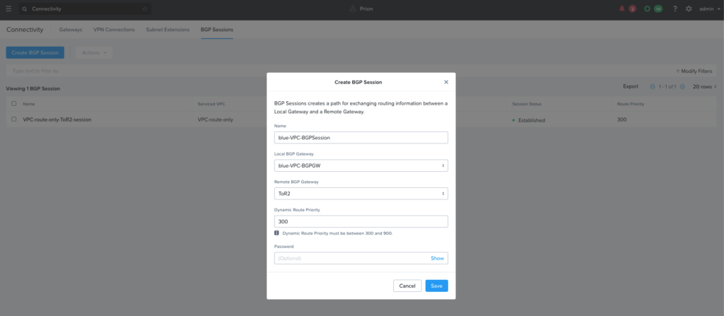
With the BGP-GW instantiated and its status indicating an “up” state, the stage is set for the creation of the BGP Session (number 4 in fig. 6).
The establishment of the BGP Session involves selecting a Remote Gateway, essential for the BGP peering process. As an example, we have created a Remote BGP Gateway, denoted as “ToR2” with AS number 65555, representing an upstream router within the infrastructure network. For the BGP session to be created, the IP address of ToR2, such as 10.10.2.5, is specified. It is worth noting that ToR2, the upstream router, includes another interface attached to the no-NAT external network, with an IP address of 10.10.1.5. This external network is the network the VPC is using for external communication.
In the context of routing within a VPC, dynamic route priorities play a significant role in determining the preferred pathways for network traffic. These priorities, ranging from 300 to 900, are assigned to BGP sessions. They enable users to strategically influence the selection of routes learned through the BGP protocol. By setting different priorities for various BGP sessions, users can fine-tune the importance of each route source, ensuring that critical paths are prioritized over fewer essential ones. This dynamic prioritization mechanism provides the flexibility to optimize routing decisions based on specific network requirements, enhancing efficiency and control over data transmission. It’s important to note that higher numbers indicate a higher level of prioritization in the routing decision-making process. In this example we specify the priority 300 to the BGP Session.
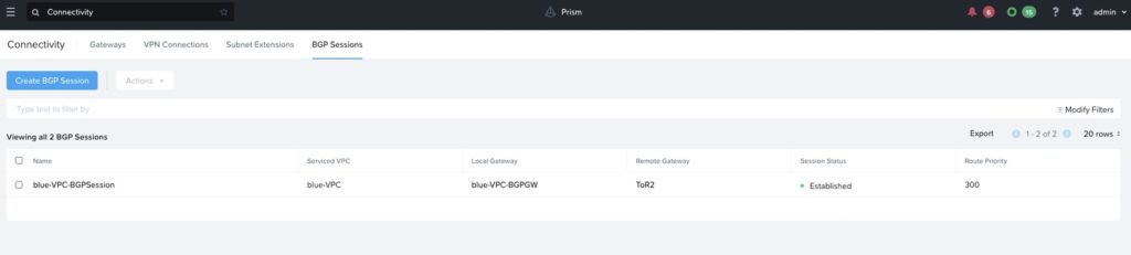
Upon successful configuration and alignment of the BGP Session with ToR2’s settings, the BGP Session attains the coveted “Established” status.
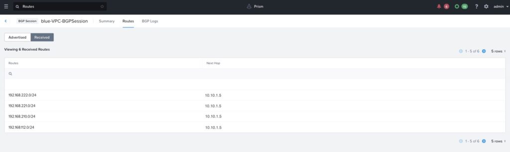
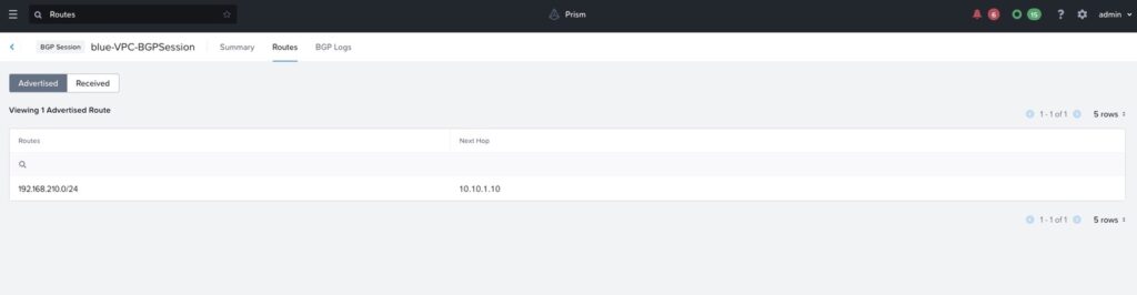
Once the BGP Session is established, a detailed exploration of its facets reveals crucial information about advertised and received routes. The ERP, such as 192.168.210.0/24, emerges as a route advertised to the broader infrastructure network through the ToR2 router. Additionally, the BGP Session exposes insights into the reception of routes from the upstream network, illuminating the symphony of data transmission and routing orchestration.
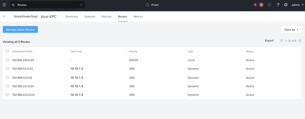
After exploring the exchanged routes through BGP sessions, a deeper dive into the VPC route table (number 5 in fig. 6) provides a comprehensive view of the intricate route management within the VPC. This consolidated route table combines local, static, and dynamic routes, each carrying distinct priorities that influence their selection during network traffic routing.
Local routes, fixed at a priority value of 65534, underpin VPC routing, ensuring streamlined communication within the internal network. Dynamic routes, received from BGP sessions, introduce an extra layer of adaptability. Their adjustable priorities allow users to precisely integrate these routes with the existing routes. For instance, in this example, routes received from the BGP Session with ToR2 has a priority of 300.
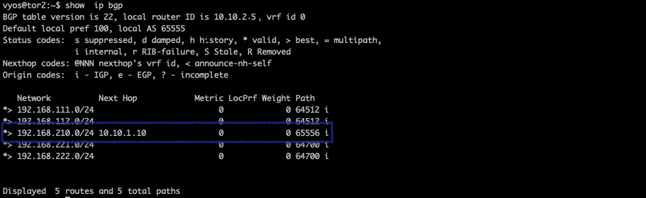
Advancing in our technical journey, an important point arises as we analyze the routes received by ToR2 from the VPC (number 6 in fig. 6). At this stage, our focus is directed towards the route to 192.168.210.0/24, which distinctly highlights 10.10.1.10/24 as its next-hop address. This specific detail tangibly illustrates the route taken by the upstream router within the data plane. This facilitates seamless access of the rest of network to the VMs within the VPC (subnet 192.168.210.0/24) using to the deployed BGP configuration.